Arduino / AVR#
TinyAVR-0/1 Programming#
I bought a couple of ATtiny412 Microcontrollers as a replacement for the trusty ATtiny85 parts that I liked to use for small projects before. Sadly, it is not available in DIP packages anymore but it also has only 8 pins.
Because I have programmed the new Arduino Nano Every and even a bare ATmega4809 chip before, I knew that there is some form of support in the Arduino suite and/or in PlatformIO.
UPDI Programmer#
Programming is done over a new protocol, called UPDI. You can flash an ATmega328P to be an
avrdude-compatible translator .. or you can simply build a very simple programming cable and
use any serial adapter. All you need to do is connect RX and TX with a resistor in series with
TX:
Serial            Device

  TX╶─╴4.7kΩ╶─╮
              ├──╴UPDI
  RX╶─────────╯
This cable can be used with pyupdi.py or
updiprog.
Blink Example with avr-gcc Compiler Toolchain#
The source code for a minimal blink example looks somewhat like this:
#include <avr/io.h>
#include <util/delay.h>

#define PIN 1
#define PERIOD 1000

int main(void) {
  PORTA.DIRSET = 1 << PIN;
  for (;;) {
    PORTA.OUTSET = 1 << PIN;
    _delay_ms(PERIOD);
    PORTA.OUTCLR = 1 << PIN;
    _delay_ms(PERIOD);
  }
}
In order to compile this for the avrxmega3 target, you’ll need to get a compatible compiler
toolchain first. My version of avr-gcc did know about the target and recognized the
-mmcu=attiny412 argument – however compilation failed because support was missing in my
copy of avr-libc. An article by Omzlo (archive)
describes the entire process in a little more detail, including how to get the necessary device
pack files from Microchip. Being an Arch Linux user, I simply installed
avr-libc-avrxmega3-svn, which
adds support for avrxmega3 by applying a patch
during compilation.
With this toolchain you can use a build process like this:
GCC_ARGS=(-mmcu=attiny412 -DF_CPU=3333333L -Os)
avr-gcc "${GCC_ARGS[@]}" -c blink.c -o blink.o
avr-gcc "${GCC_ARGS[@]}" blink.o -o blink.elf
avr-objcopy -O ihex -R .eeprom blink.elf blink.hex
updiprog -d tiny41x -c /dev/ttyUSB0 -e -w blink.hex
Adding Baremetal Support in PlatformIO#
Support can also be added to PlatformIO with a custom board definition and a modified
upload_command. The compiler toolchain that is used for the atmelmegaavr platform
already has support for this family because they are very similar to the Arduino Nano
Every and ATmega4809 mentioned above.
Add the file attiny412.json in a subdirectory boards/ of
your PlatformIO project and use board = attiny412 in the config file along with a
new upload_command:
[env:tinyavr]
platform = atmelmegaavr
board = attiny412
upload_command = updiprog -d tiny41x -c $UPLOAD_PORT -b $UPLOAD_SPEED -e -w $SOURCE
It should be trivial to adjust the board definition for other microcontrollers in the same family.
Alternative for Baremetal Support in PlatformIO#
Another alternative to creating a full board JSON is simply not specifying a board
at all, apparently. I have successfully used this platformio.ini to program and flash
an ATmega16U2 (that is the “USB-to-Serial” chip on an Arduino Uno R3 .. yes, you have
two microcontrollers on that board):
[env:atmega16u2]
platform = atmelavr
board_build.mcu = atmega16u2
board_build.f_cpu = 16000000UL
board_upload.maximum_size = 16384
board_upload.maximum_ram_size = 512

upload_protocol = custom
upload_flags =
  -cusbtiny
  -pm16u2
upload_command = /usr/bin/avrdude $UPLOAD_FLAGS -U flash:w:$SOURCE:i
Note: if you’re going to play with the ATmega16U2 on your Arduino UNO R3, I have
a firmware dump of mine
if you need to restore its full functionality later. There may be quirks about
the protected USB bootloader region. The original “combined” firmware can be found
in your Arduino installation’s firmware data:
~/.arduino15/packages/arduino/hardware/avr/1.8.1/firmwares/atmegaxxu2
Flashing over ISP header#
Recently I had the need to program an Arduino that was not responding over USB, i.e. the bootloader was probably broken somehow. I wrote a blog entry about that.
The usual ISP header on an Arduino is mapped like this:
     ┏─────╮
MISO │ 1 2 │ VCC
 SCK │ 3 4 │ MOSI
 RST │ 5 6 │ GND
     ╰─────╯
Sparkfun FTDI FT232R Breakout Board#
The FT232R provides a straightforward “bit-bang” mode to drive these pins. Some breakout boards come with an ISP header directly soldered on but you can also just use the breadboard pins on a full breakout. I’m using a Sparkfun FT232R Breakout to do this.
These are the pins of a FT232R which correspond to the above ISP header:
     ┏─────╮
 CTS │ 1 2 │ VCC
 DSR │ 3 4 │ DCD
  RI │ 5 6 │ GND
     ╰─────╯
On the bottom of the Sparkfun breakout the legs are mapped like this:
         USB
┏───────────────────╮
│ ■ DCD     PWREN □ │
│ ■ DSR     TXDEN □ │
│ ■ GND     SLEEP □ │
│ ■ RI        CTS ■ │
│ □ RXD      V3.3 □ │
│ □ VCCIO     VCC ■ │
│ □ RTS     RXLED □ │
│ □ DTR     TXLED □ │
│ □ TXD       GND □ │
│      □ □ □ □      │
╰───────────────────╯
This configuration should come shipped with a decently modern avrdude version
already. If it’s not, here is a copy:
# see http://www.geocities.jp/arduino_diecimila/bootloader/index_en.html
# Note: pins are numbered from 1!
programmer
  id    = "arduino-ft232r";
  desc  = "Arduino: FT232R connected to ISP";
  type  = "ftdi_syncbb";
  connection_type = usb;
  miso  = 3;  # CTS X3(1)
  sck   = 5;  # DSR X3(2)
  mosi  = 6;  # DCD X3(3)
  reset = 7;  # RI  X3(4)
;
Using avrdude like this is said to be slower than other methods but in my testing it
turned out to be decently quick – not “minutes” like some comments suggest anyway.
avrdude -c arduino-ft232r -p m328p -v
Adafruit FTDI FT232H Breakout Board#
Even better, the FT232H provides a proper MPSSE SPI interface. I mentioned above that
bit-banging is said to be slower but I didn’t perceive it as too bad. Oh it does make
a difference! Performing a simple benchmark with successive readout and writebacks of
the eeprom and flash areas on an Arduino Nano clone took 16 seconds using the
FT232H while it took over two minutes on the FT232R.
Looking from the top, the pins on the Adafruit board are used like this:
USB
┏──────────────────╮
│ ■ 5V C9 □ │
│ ■ GND C8 □ │
│ ■ D0 SCK C7 □ │
│ ■ D1 MOSI C6 □ │
│ ■ D2 MISO C5 □ │
│ ■ D3 RST C4 □ │
│ □ D4 C3 □ │
│ □ D5 C2 □ │
│ □ D6 C1 □ │
│ □ D7 C0 □ │
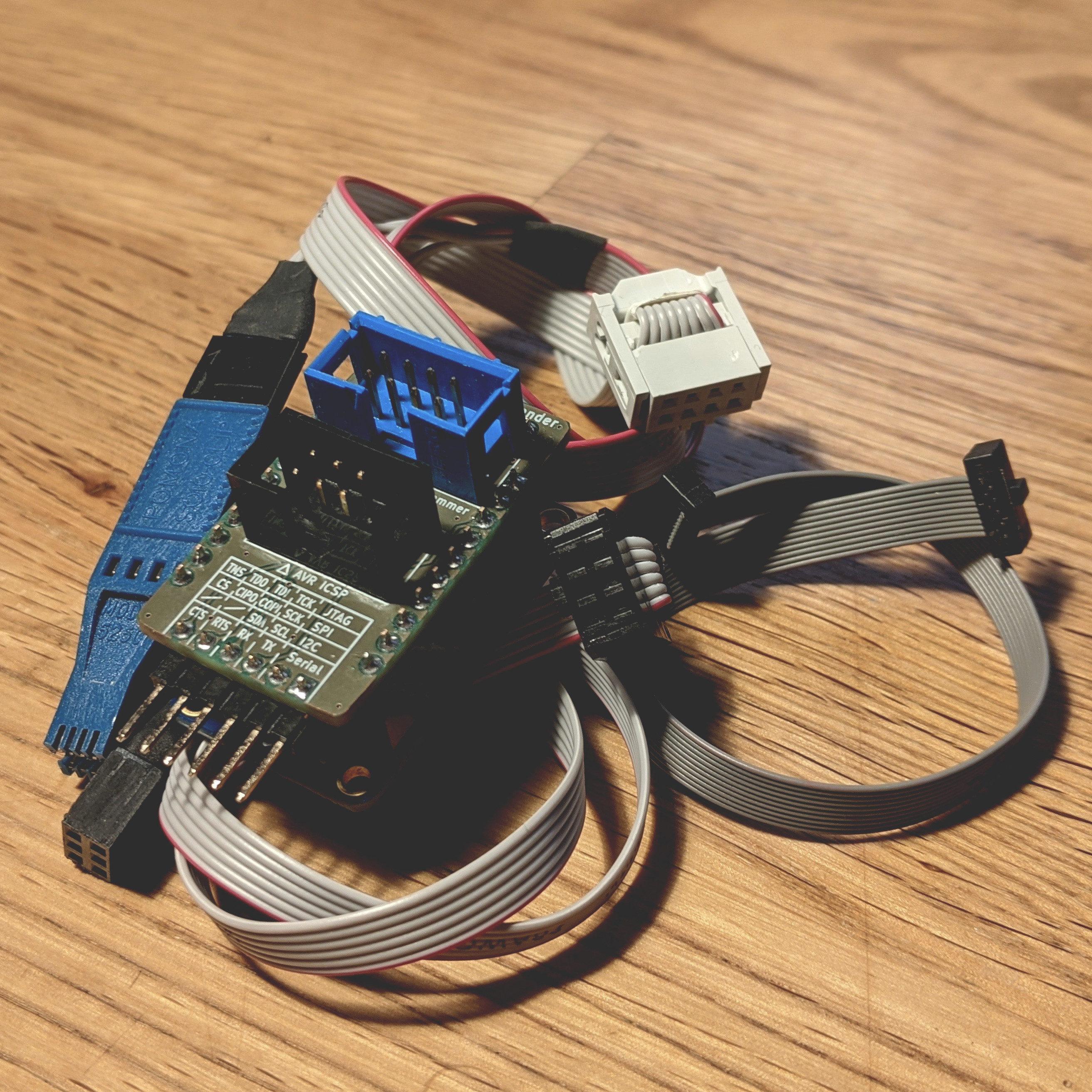
╰──────────────────╯The pins are all nicely in one row, so you can easily craft a custom cable, too. I also created a small “expander” for the FT232H, which adds headers for AVR ICSP, 8-SOIC flash clip cables and a 1.27 pitch JTAG connector. Check it out on GitHub: ansemjo/ftdi-expander.
The avrdude config was first described on helix.air.net.au and is now integrated in the
systemwide config as programmer UM232H:
# UM232H module from FTDI and Glyn.com.au.
# See helix.air.net.au for detailed usage information.
# /* ... */
# Use the -b flag to set the SPI clock rate eg -b 3750000 is the fastest I could get
# a 16MHz Atmega1280 to program reliably.  The 232H is conveniently 5V tolerant.
programmer
  id         = "UM232H";
  desc       = "FT232H based module from FTDI and Glyn.com.au";
  type       = "avrftdi";
  usbvid     = 0x0403;
  usbpid     = 0x6014;
  usbdev     = "A";
  usbvendor  = "";
  usbproduct = "";
  usbsn      = "";
#ISP-signals
  sck    = 0;
  mosi   = 1;
  miso   = 2;
  reset  = 3;
;
I’ve created two straightforward programmer aliases in my ~/.avrduderc config and
can use these two breakout boards with avrdude -c ft232r and avrdude -c ft232h
respectively:
# alias for adafruit ft232h
programmer parent "UM232H"
  id         = "ft232h";
  desc       = "Adafruit FT232H based SPI programmer";
;

# alias for sparkfun ft232r breakout
programmer parent "arduino-ft232r"
  id         = "ft232r";
  desc       = "Sparkfun FT232R breakout bit-banging";
;
Note about the new Revision with USB-C#
There’s a newer revision of the Adafruit FT232H, which has a USB-C receptacle and Qwiic connector.
This board also has a switch to enable the I2C mode by connecting D1 and D2 together!
Make sure this switch is OFF when you’re trying to flash your Arduino. Otherwise you will
only get constant 0x535353 bytes back! This tripped me up because it was neither random nor
constant ones or zeroes, until I remembered that switch. Doh'!
$ avrdude -c ft232h -p attiny85

avrdude: AVR device initialized and ready to accept instructions

Reading | ################################################## | 100% 0.00s

avrdude: Device signature = 0x535353
avrdude: Expected signature for ATtiny85 is 1E 93 0B
         Double check chip, or use -F to override this check.
Raspberry Pi#
At the time, however, I used the GPIO pins on a Raspberry Pi Zero W and amended the
avrdude configuration to use bit-banging as well. Here is a possible
mapping of the GPIO pins on the 40-pin header:
                15 ┆ · · ┆ 16
          3.3V  17 │ x · │ 18
(GPIO 10) MOSI  19 │ x x │ 20  GND
(GPIO 09) MISO  21 │ x x │ 22  Reset (GPIO 25)
(GPIO 11) SCLK  23 │ x · │ 24
                25 ┆ · · ┆ 25
This wiring can be used with the following avrdude programmer configuration:
# avr programmer via linux gpio pins
programmer
  id    = "gpio";
  desc  = "Use the Linux sysfs to bitbang GPIO lines";
  type  = "linuxgpio";
  reset = 25;
  sck   = 11;
  mosi  = 10;
  miso  = 9;
;
Put that in ~/.avrduderc or a seperate file, which can be included with
avrdude -C +gpio.conf .... Now use this programmer config like this:
sudo avrdude -c gpio -p m1284p -v